|
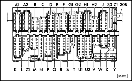
A1
|
Yellow
|
8 pin
|
Headlight wiring harness
|
|
A2
|
Yellow
|
8 pin
|
Headlight wiring harness
|
|
B
|
Green
|
6 pin
|
Headlight washer wiring harness
|
|
C
|
Yellow
|
8 pin
|
Headlight or wiper motor wiring harness
|
|
D
|
Green
|
12 pin
|
Miscellaneous equipment, varies (A/C, A/T, heated seats, seat belt warning, etc.)
|
|
E
|
Green
|
5 pin
|
Instrument or brake light wiring harness
|
|
F
|
White
|
10 pin
|
Engine compartment/engine management, wiring harness, right side (position 10 open)
|
|
G1
|
White
|
12 pin
|
Engine compartment/engine management, right side
|
|
G2
|
White
|
12 pin
|
Engine compartment/engine management, right side (position 12 open)
|
|
H1
|
Red
|
10 pin
|
Steering column switch wiring harness
|
|
H2
|
Red
|
8 pin
|
Steering column switch wiring harness (position 8 open)
|
|
J
|
Red
|
10 pin
|
Steering column switch wiring harness
|
|
K
|
Black
|
12 pin
|
Rear wiring harness
|
|
L
|
Black
|
8 pin
|
Rear/Parking brake wiring harness (position 8 open)
|
|
M
|
Black
|
6 pin
|
Rear/fuel tank wiring harness
|
|
N
|
Green
|
6 pin
|
Air conditioning wiring harness
|
|
P
|
Blue
|
10 pin
|
Rear window defroster/fog light wiring harness
|
|
Q
|
Blue
|
6 pin
|
Fresh air blower fan wiring harness (position 10 open)
|
|
R
|
Blue
|
10 pin
|
Light switch wiring harness
|
|
S
|
White
|
5 pin
|
Engine compartment/wiper motor wiring harness, right side
|
|
T
|
Green
|
2 pin
|
Individual circuits
|
|
U1
|
Blue
|
14 pin
|
Instrument cluster wiring harness
|
|
U2
|
Blue
|
14 pin
|
Instrument cluster wiring harness
|
|
V
|
Green
|
4 pin
|
Steering column switch Multi-function indicator wiring harness
|
|
W
|
Green
|
6 pin
|
Miscellaneous optional equipment, varies with vehicle type
|
|
X
|
Green
|
8 pin
|
Warning lamp wiring harness
|
|
Y
|
n/a
|
1 pin
|
4 single point connectors for terminal 30 circuit (some may be bridged with red connector)
|
|
Z1
|
n/a
|
1 pin
|
Single point connector
|
|
Z2
|
n/a
|
1 pin
|
Single point connector for terminal 31 circuit
|
|
30
|
n/a
|
1 pin
|
Single point connector for terminal 30 circuit (may be bridged to 30B with red connector)
|
|
30B
|
n/a
|
1 pin
|
Single point connector for terminal 30 circuit (may be bridged to 30 with red connector)
|
![[B] Bentley Publishers](http://assets1.bentleypublishers.com/images/bentley-logos/bp-banner-234x60-bookblue.jpg)
